


Drones have become increasingly popular for hobbyists and professionals alike. With advancements in microcontrollers, building a drone at home has become more accessible. However, drone making can be expensive due to the cost of components such as flight controllers, dedicated transmitters, and high-end sensors. By using an ESP32 microcontroller and leveraging a smartphone as the transmitter, we can significantly reduce the total cost of building a drone without compromising on functionality. In this article, I am showing how you can build a simple drone for below 15$ or 1500 rs.
Components Required:
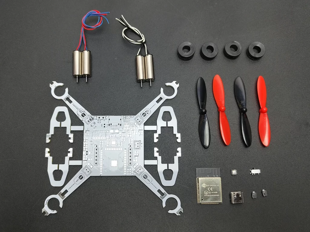
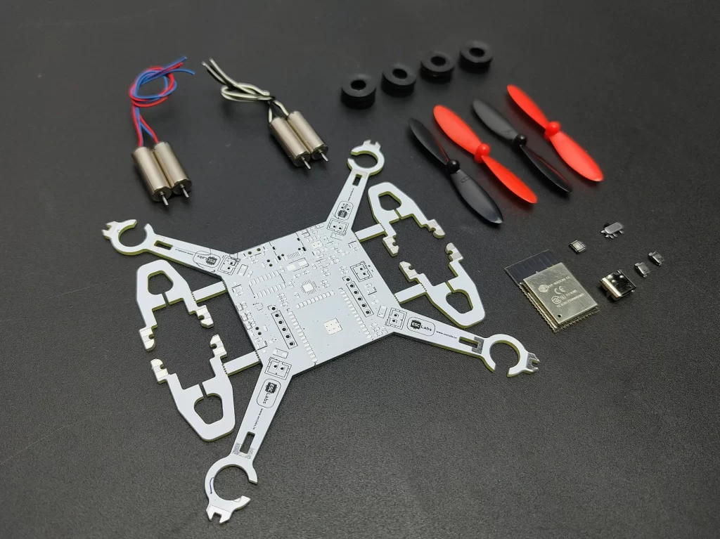
These are the main components required to make this drone. all other complimentary components of the list can be found in the below-given link
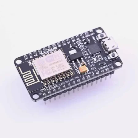
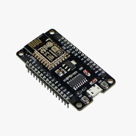
- ESP32-WROOM-32 – The brain of the drone, responsible for communication and control.
- MPU-6050 IMU (Inertial Measurement Unit) Sensor – Provides real-time orientation data.
- Coreless Motors (4x) – Provide the necessary thrust for flight.
- SI2302DS MOSFET (4x) – To drive the four motors.
- Propellers (2x CW, 2x CCW) – Generate lift and stability.
- 3.7v -25C-Li-Po Battery – Powers all components.
- Custom Drone PCB
you can buy all the components from here
you can download the complete BOM file here
Tools required
- Soldering iron
- Hotplate for reflow
- wires
CIRCUIT DIAGRAM
download the circuit diagram from here
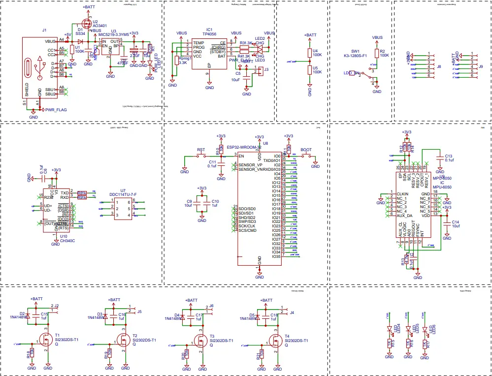
The given schematic includes power management, a microcontroller (ESP32-WROOM), a USB-to-serial interface, a gyro sensor (MPU6050), and MOSFET-based switching circuits. Each section of the schematic plays a critical role in ensuring the functionality of the drone.
The ESP32-WROOM module serves as the central processing unit of this circuit, providing computation, control, and communication capabilities. It operates on a 3.3V supply, which is derived from the MIC5219 voltage regulator. To ensure proper operation, the ESP32 includes several supporting components: the reset button (RST) is connected to the EN (Enable) pin, allowing the user to reset the microcontroller boot button is connected to GPIO0, enabling the ESP32 to enter boot mode when necessary, especially for flashing new firmware. Communication with external peripherals is established through various GPIO pins. Some of the key connections include:
- I2C Interface (GPIO21 for SDA and GPIO22 for SCL), is used to communicate with the MPU6050 motion sensor.
- UART Interface (TXD and RXD), which connects to the CH340C USB-to-serial converter, allows serial communication with a computer.
The circuit includes a CH340C USB-to-serial converter to facilitate communication between the ESP32 and an external computer. This interface is essential for programming and debugging the microcontroller. The CH340C receives power from the 3.3V rail, ensuring compatibility with the ESP32. The TXD (transmit data) pin of the CH340C is connected to the RXD (receive data) pin of the ESP32, while the RXD pin of the CH340C is connected to the TXD pin of the ESP32. This allows bidirectional serial communication. To support auto-reset functionality, the RTS (Request to Send) pin of the CH340C is connected to the ESP32’s EN pin, which allows the system to automatically reset the microcontroller when flashing new firmware. Additionally, a power switch IC (DDC114TU) is incorporated to manage power flow to the USB-to-serial interface.
The schematic also includes an MPU6050 inertial measurement unit (IMU) sensor, which provides accelerometer and gyroscope data. This data is crucial for stability of the drone The MPU6050 operates on a 3.3V power supply, which it receives from the voltage regulator. It communicates with the ESP32 via the I2C protocol, using:
- SDA (Serial Data Line) → ESP32 GPIO21
- SCL (Serial Clock Line) → ESP32 GPIO22
In addition to the standard data lines, the circuit incorporates pull-up resistors to ensure proper signal integrity, and decoupling capacitors (C13, C14) to stabilize the power supply, minimizing noise and fluctuations.
The power management section is responsible for providing a stable power supply to the entire circuit. The circuit utilizes a USB input (J1), which serves as the primary power source. The USB’s 5V output is first directed through a Schottky diode (D2 – SS34) to prevent reverse current flow, ensuring the protection of upstream components. To regulate the voltage for low-power components, the circuit employs a MIC5219-3.3V voltage regulator (U5). This regulator steps down the USB’s 5V input to a stable 3.3V, which powers critical components such as the ESP32 microcontroller and the MPU6050 sensor.
In addition to direct power regulation, the system includes a TP4056 battery charging IC (U6) to facilitate the charging of a Li-ion battery. The TP4056 module takes input from the USB’s 5V supply and manages the battery’s charging process efficiently. Several resistors (R31, R34, R36) and LEDs (LED2, LED3) are included in the design to indicate charging status, with one LED lighting up when the battery is charging and the other when it is fully charged.
To reduce the total cost we are not using any electronic speed controllers here. The schematic includes four SI2302DS-T1 MOSFETs (T1, T2, T3, T4), which act as electronic switches for controlling four motors.
Additionally, 1N4148 diodes (D2, D3, D4, D5) are placed across each MOSFET to protect against voltage spikes.
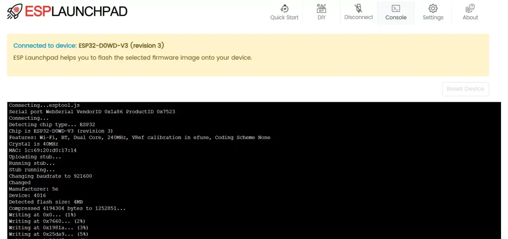
To upload code to esp32 I am using esp launchpad here. First, go to esp launchpad and click on connect then select the com port. Now you can see it is connected. Now go to DIY and select the flash address to zero. Then select the file from your computer. Now click on Flash. It will take 30 seconds to flash the code. Then reset the drone. Then you can see the success message on the console. thats it.
download the flash file from here
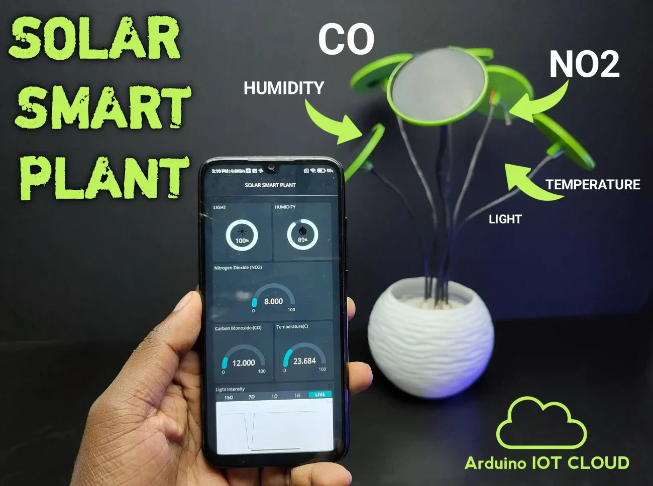
APPLICATION
download app from here


Leave a comment