


Hello there, If you are an electronics enthusiast then you should be familiar with PCBs or Printed Circuit Boards. But may all of you be familiar with flexible PCBs. So Flexible PCBs or flex PCBs, are circuit boards designed to be bent, twisted, or shaped to fit into tight or irregular spaces. Unlike traditional rigid PCBs, flexible PCBs are made from materials that allow the board to flex without damaging the circuits. Here are some key features and advantages of flexible PCBs Flexible PCBs are usually made from polyester films, which provide flexibility while maintaining excellent electrical insulation properties. Just like rigid PCBs, flexible PCBs use copper as the conductive material, deposited into the flexible substrate. Despite their flexibility, flex circuits are designed to maintain their performance even in dynamic applications where movement is frequent.
Advantages of flexible PCBs:
- Space and Weight Saving: Flexible PCBs can be folded or twisted to fit into small or irregularly shaped enclosures, making them ideal for compact devices.
- Durability: They are highly resistant to vibrations and movement, making them suitable for dynamic applications like wearable electronics, robotics, or automotive systems.
- Reduced Connectors and Assembly: Because they can replace traditional wiring harnesses, flexible PCBs reduce the need for bulky connectors and additional assembly.
- Improved Heat Dissipation: Polyimide and other materials used in flex PCBs have good thermal properties, helping to manage heat better in tight spaces.
Applications of flexible PCBs:
- Wearable Technology: Smartwatches, fitness trackers, and other wearable devices.
- Medical Devices: Implantable devices and diagnostic equipment.
- Automotive: Flex circuits are used in dashboards, sensors, and under-the-hood electronics.
- Aerospace: Aerospace is used in avionics due to its lightweight and high reliability.
- Consumer Electronics: Smartphones, cameras, and other portable devices use flex PCBs for compact designs.
So these are the basic features and applications of a flexible PCB. So in this project, I am going to show you how we can build a flexible Arduino. I will explain all the details of this project in detail in the following sections. You may ask why I chose Arduino for this or what the need for a flexible Arduino is. Well, the answer is I love to build clones of Arduino Unos also Arduino uno is open source and we can modify it. Now let’s get started.
Modifying the Original Schematic
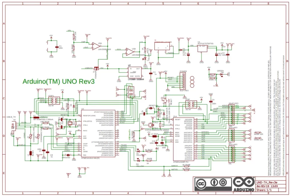
Here you can see the traditional Arduino uno circuit. the circuit seems very complicated at first. But we can reduce the component count and rectify the circuit.
I used easyeda to recreate the circuit diagram for our Arduino. EasyEDA is a popular web-based tool for designing and simulating electronic circuits and PCBs. It is completely free and easy to use. that means beginner friendly.
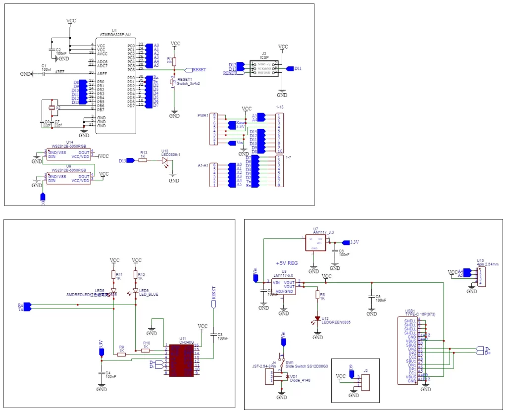
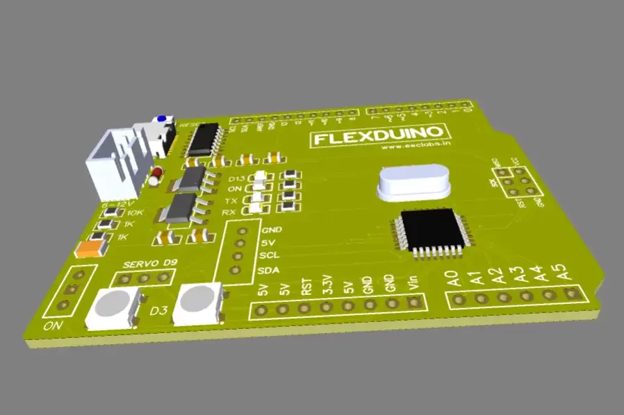
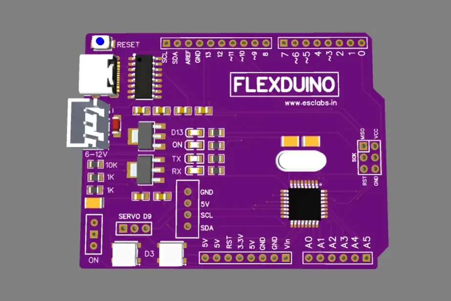
These are the changes that I made in the traditional Arduino uno circuit.
The circuit uses a DIP atmega328 IC as a microcontroller. Here I wanted to flex the Arduino so I replaced the DIP version with SMD.
The traditional board uses a USB type B socket for programming. Nowadays no one is using that connector also that is bulky., so I replaced it with Type C USB.
The existing board uses the ATmega16U2 to convert USB signals to serial communication (UART) that the ATmega328P can understand, allowing you to program the Arduino from your computer. To reduce the cost I replaced the ATmega16U2 with CH340.
Added two WS2812B neopixel LEDs
Added on/off switch
Added JST connector for external power supply.
After changing these things in the original circuit I finalized the circuit. The next is to convert the circuit diagram into PCB.
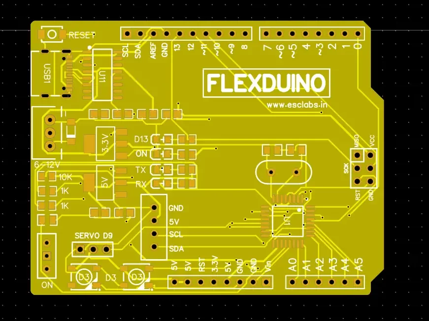
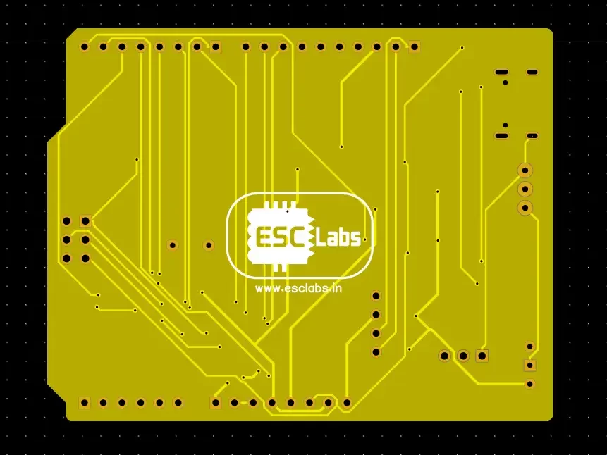
PCB Designing
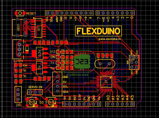
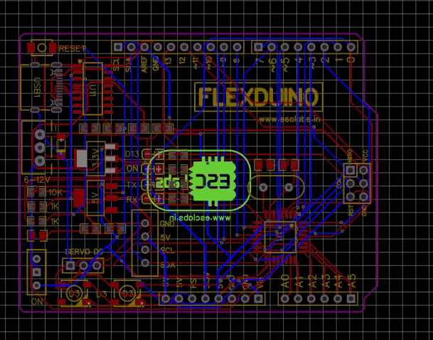
we are making flexible PCB. But that doesn’t mean we need to design a flexible PCB. We can design PCB just like any other PCB. In the easyeda, we can directly convert the circuit diagram into PCB. So I used the tool and convert the circuit into a PCB. Now I used the same outline of Arduino. I downloaded that Google and I added that as an image. Then I drew the outline on that. After making the outline I arranged the components. I used the original Arduino as a reference and arranged the components according to that. After completing the design of the PCB I downloaded the Gerber files for PCB fabrication.
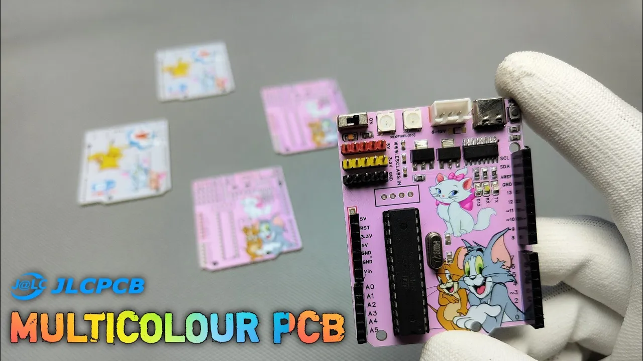
PCB Fabrication
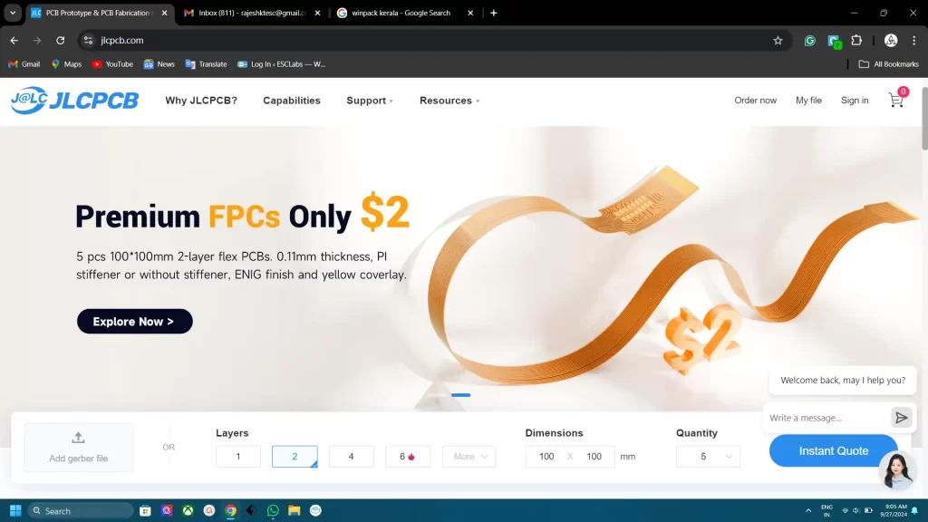
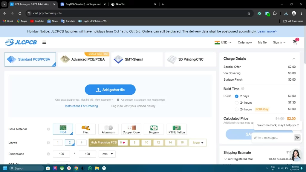
The next step is the fabrication of the designed PCB. we need a fabrication service which offers flexible PCB manufacturing. For that, I went to jlcpcb.com. they are the best PCB manufacturers and they offer only 2 dollars for 5 flexible PCBs and their PCB assembly starts from zero dollars. PCB ordering from JLCpcb is very easy. Click on Order now- select the and upload the Gerber file. Now select flex as base material.
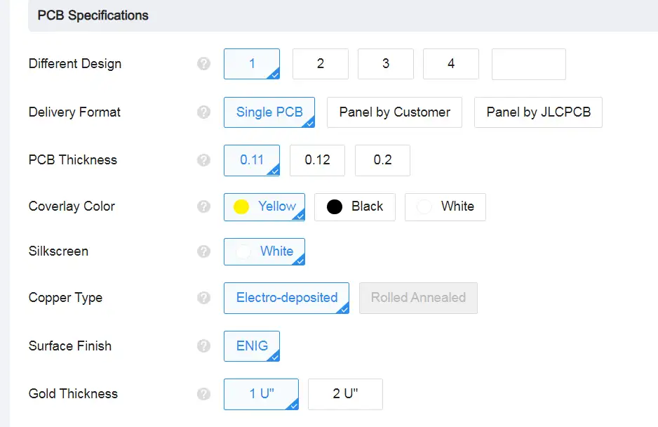
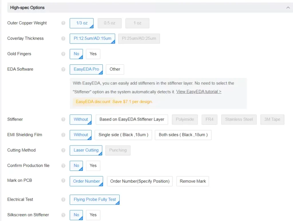
in the PCB specifications, we can select the thickness of the PCB, PCB colour, silkscreen etc. Also in high-spec options, we can add stiffener type, gold fingers EMI shielding etc. Since we are just making a basic circuit we are not going to select any of that. also adding those parameters will increase the PCB cost too. so after selecting all the details we can select the correct shipping address and shipping method then we can place the order.
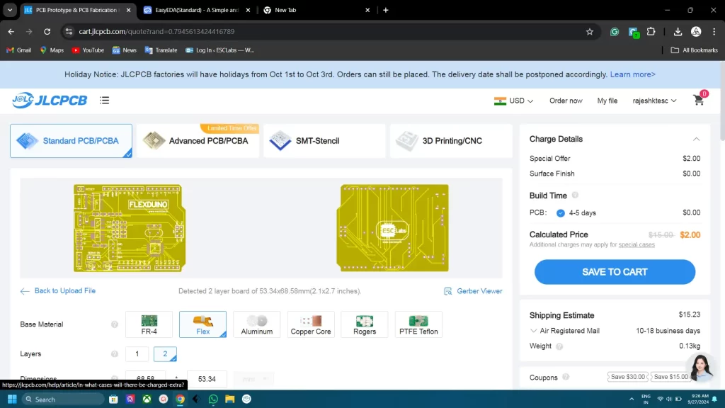
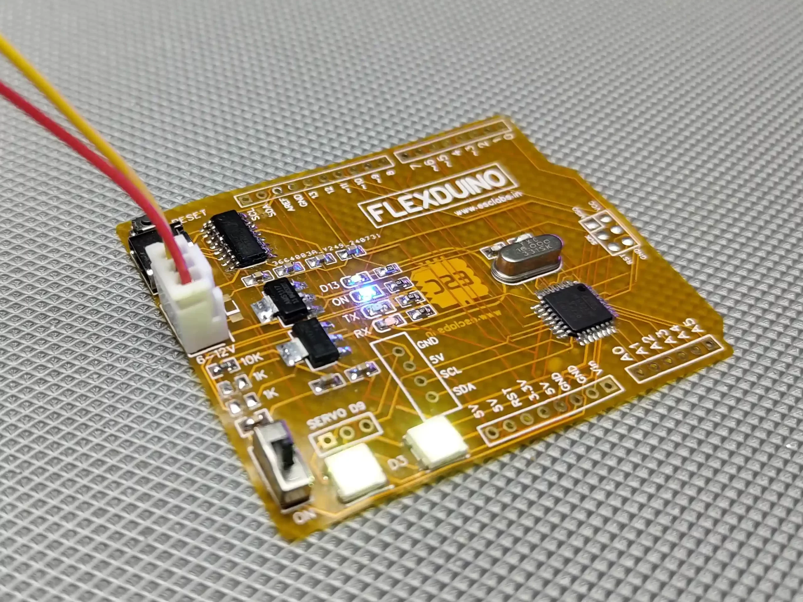
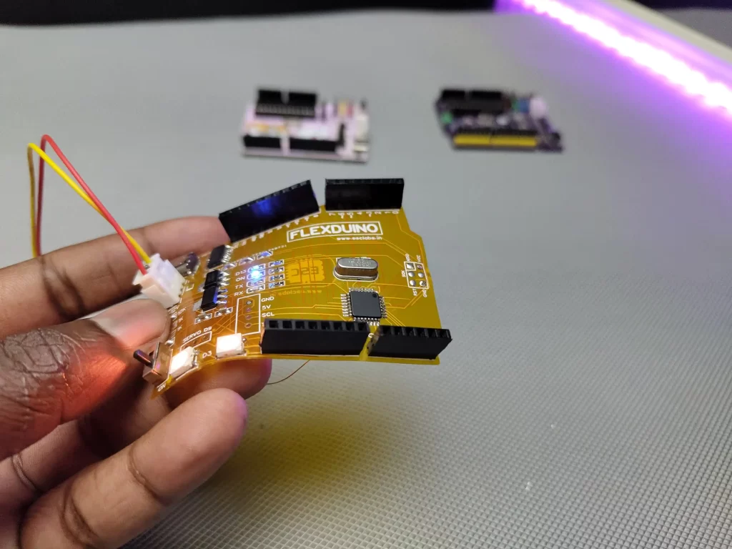
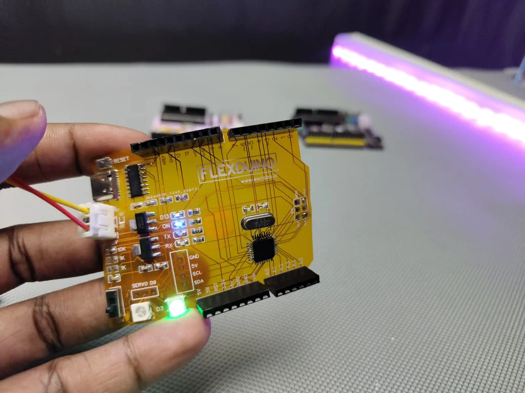
The flexible PCBs
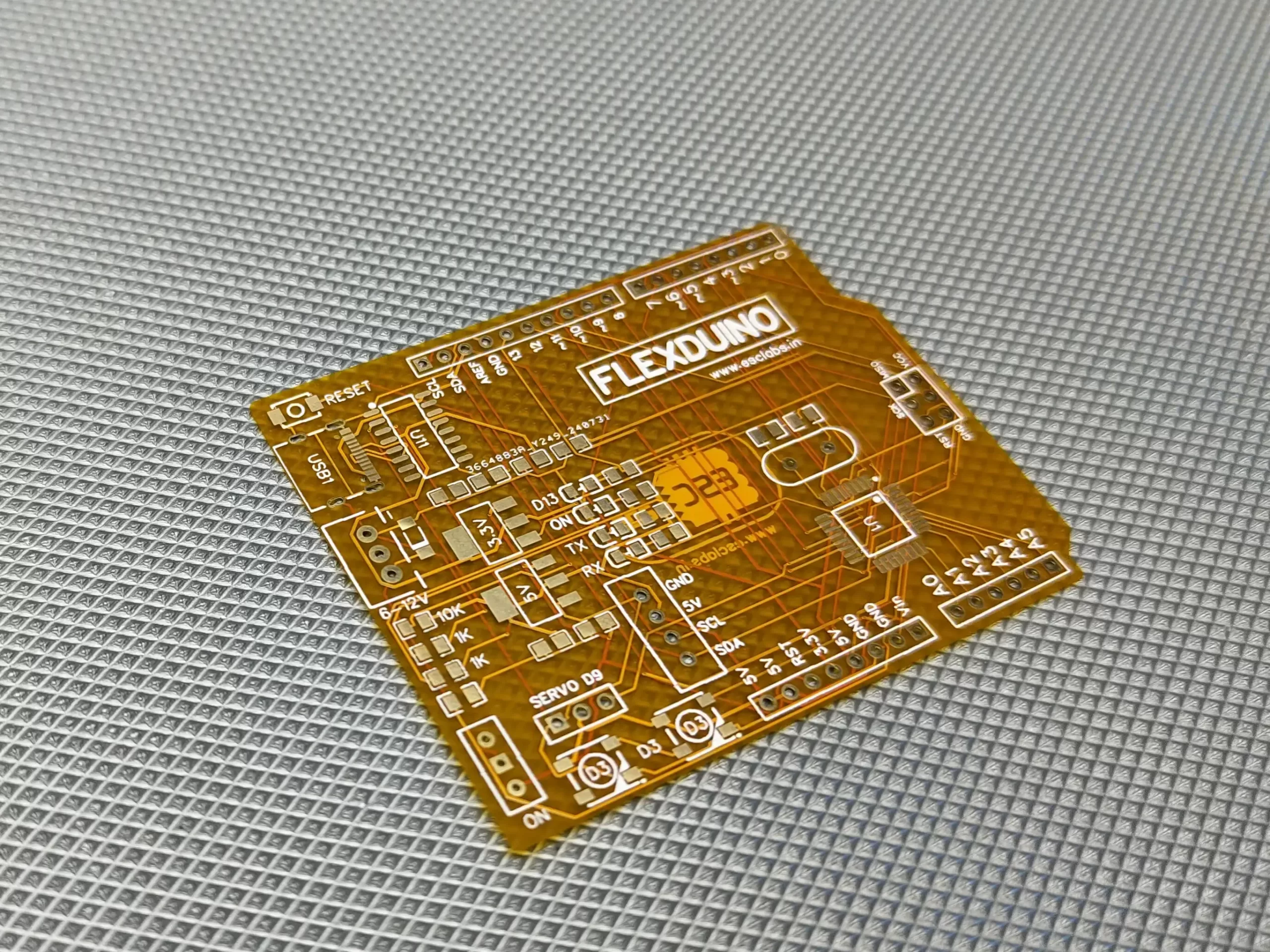
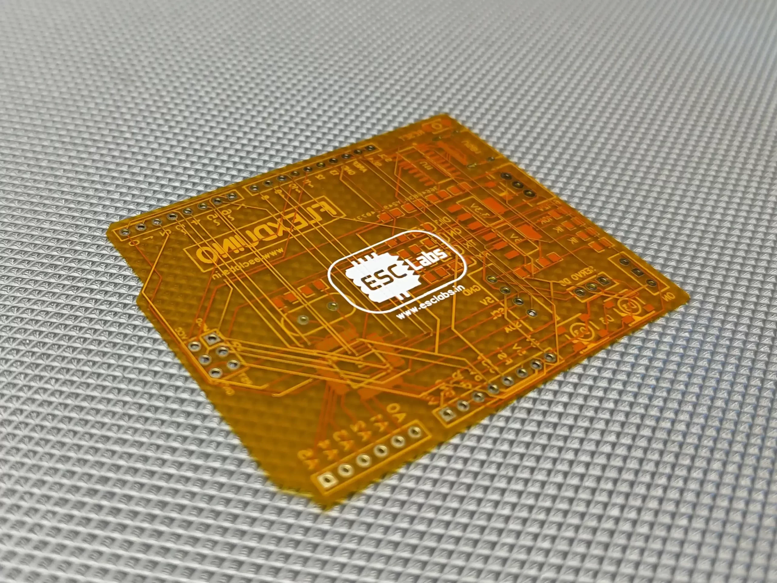
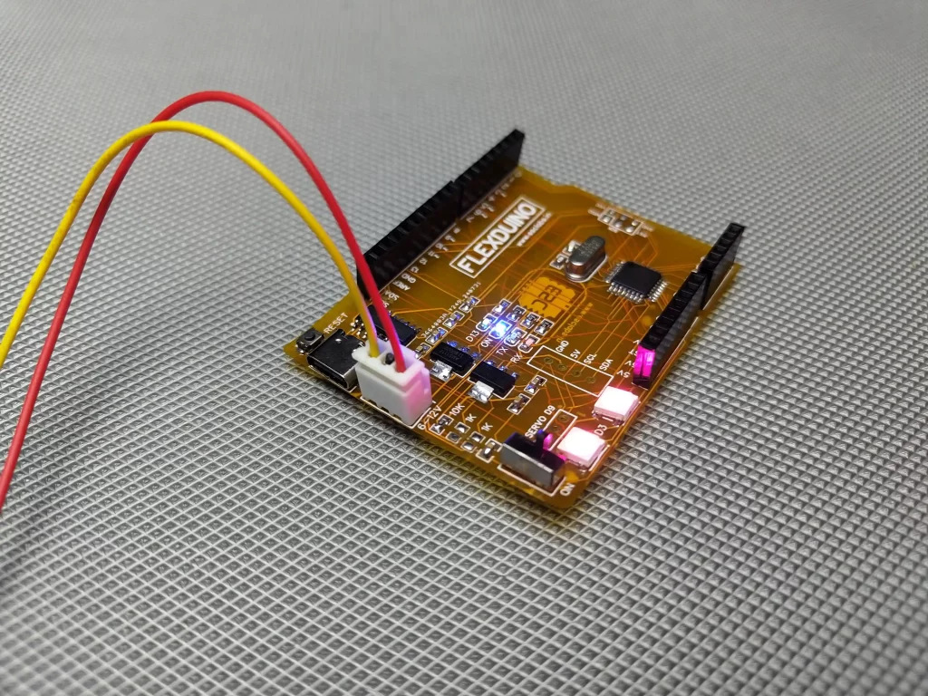
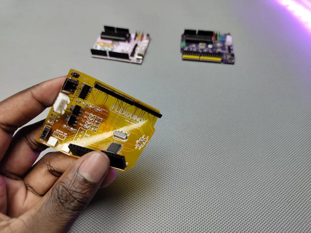
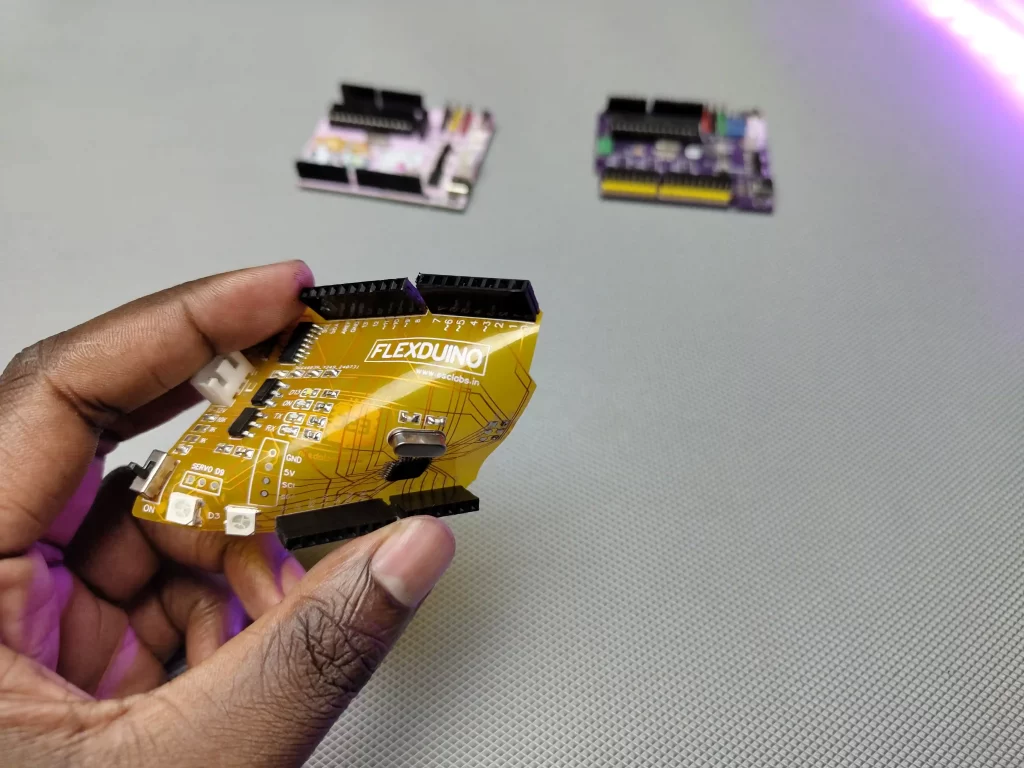
After 10 days I received the fabricated PCBs from jlcpcb. the PCBs came well packed and package quality is outstanding. The PCBs are perfectly printed. the flexibility of printed PCB is great. Nice job jlcpcb.
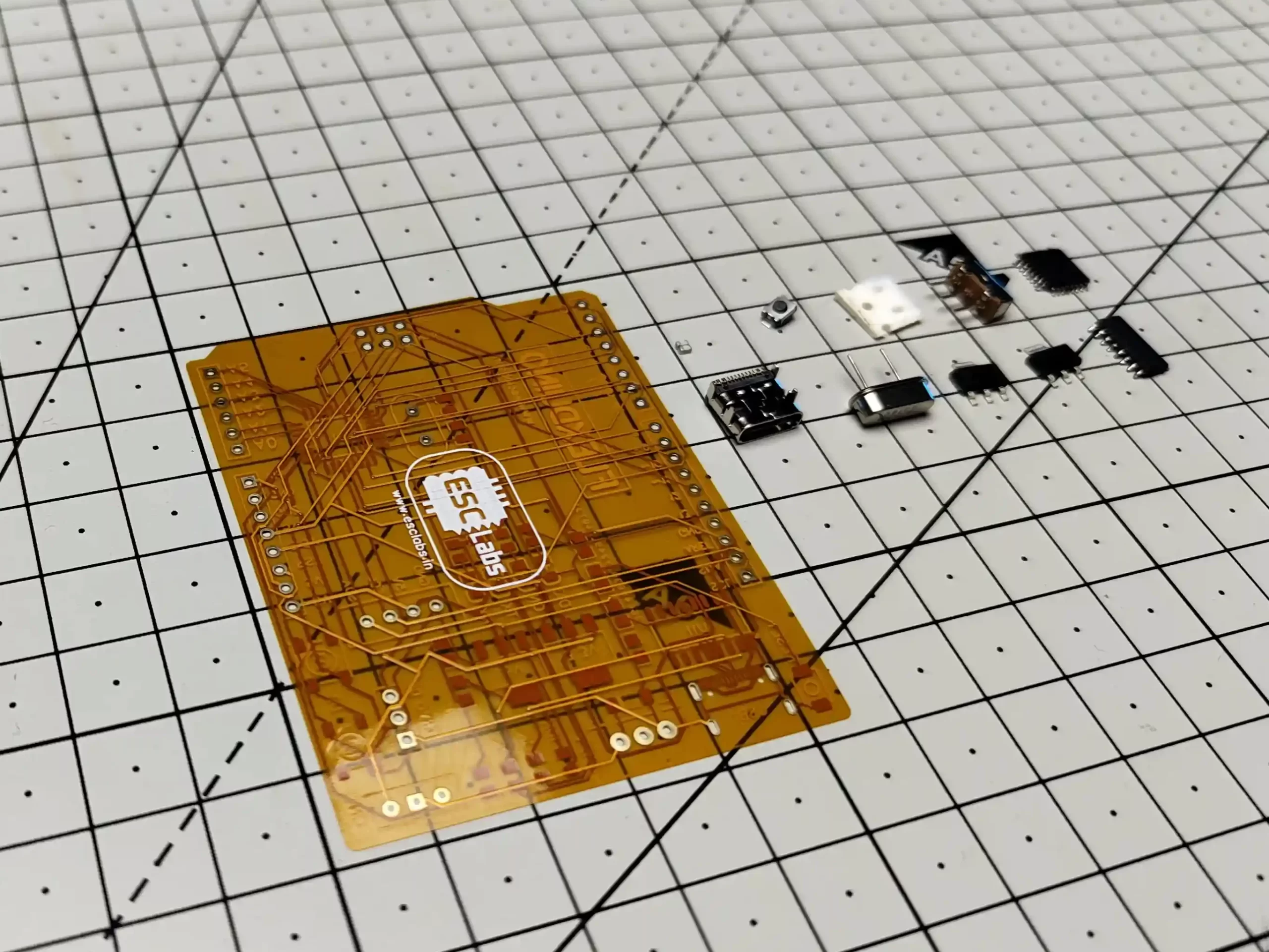
Components Needed for Making the ARDUINO
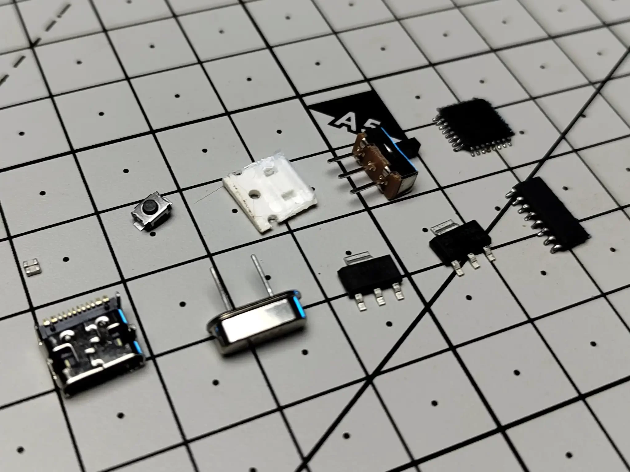
- Atmel Atmega328 Microcontroller
- CH340C USB to TTL converter
- 16MHz crystal oscillator
- 0805 22pF caps X 2 nos
- 0805 100nF caps X 4 nos
- 0805 LED X 4 nos
- WS2812B neopixel LED X 2 nos
- 1K 0805 resistor X 4 nos
- 10K 0805 resistor X 1 nos
- reset switch
- 1N4148 SMD diode
- AMS1117 5.0V Linear voltage regulator
- AMS1117 3.3V Linear voltage regulator
- 2.54mm 3-pin JST
- USB type C port
- Female header pins
- on/off switch
These are the components that you need to make this project. Wherever quantity is not mentioned consider it as one. Except for these, you will also need soldering equipment and some hardware tools to make the build easier.
I used my miniware soldering iron to solder all components to the flexible Arduino. I set the temperature to 315 degrees in the soldering iron. You can also use the hotplate method or reflow method to solder all components. don’t use sharp tools on the PCB it will easily damage the PCB. Also, make sure to complete the soldering as soon as possible. I started with the main Atmega328 IC and then I soldered all other SMD components. you can finish the soldering in just 30 minutes. after finishing the soldering I cleaned the PCB with IPA. after doing all this we can use this board just as normal Arduino UNO.
in this article, I showed how you can build a flexible PCB. With this, you can build different projects and tools. In the next flexible PCB project, I will show you how to build a flexible RGB display.
Support Us : Amazon Affiliate Link
Complete Video Tutorial

Leave a comment